 TUR
































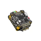
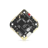
SpeedyBee F7 V3 BL32 50A 30x30 Stack

- Power Input (FC and ESC): 3-6S LiPo
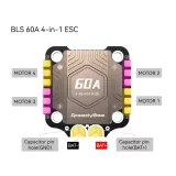
- Continuous Current (ESC): 50A * 4
- Mounting (FC and ESC): 30.5 x 30.5 mm (4 mm hole diameter)
- Dimensions: (FC) 41(L) x 38(W) x 8.1(H)mm - (ESC) 45.6(U) * 40(G) * 8.8mm(Y)
- Weight: (FC) 10.7g - (ESC) 19.2g with heatsink
- PWM Frequency Range: (ESC) 16KHz-128KHz
1. Open STACK Manual in a New Tab
Click here to open the STACK Manual in a new tab2. Download STACK Manual
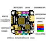
Click here to download the STACK ManualMCU (FC):
STM32F722
IMU(Gyro)(FC):
BMI270
USB Port Type (FC):
Type-C
Barometer (FC):
BMP280
OSD Chip (FC):
AT7456E chip
BLE Bluetooth (FC):
Supported. Used for flight controller configuration, a single integrated 2.4 GHz Wi-Fi and Bluetooth combo chip.
DJI Air Unit Connection Way (FC):
Two supported paths: 6-pin connector or direct soldering.
6-pin DJI Air Unit Plug (FC):
Supported. Fully compatible with DJI O3/RunCam Link/Caddx Vista/DJI Air Unit V1, no cables need to be replaced.
Flash(for BlackBox) (FC):
500MB
BetaFlight Camera Control Pad (FC):
Yes (CC pad on the front)
Power Input (FC):
3S - 6S Lipo
5V Output (FC):
On the front, 10 groups of 5V output, three +5V pads, and one BZ+ pad (used for buzzer) and 6 +5V outputs on the connectors at the bottom. Total current load is 2A.
9V Output (FC):
2 groups of 9V output, one +9V pad on the front and another in a connector at the bottom. Total current load is 4A.
3.3V Output (FC):
Supported. Designed for 3.3V input receivers. Current load up to 500mA.
4.5V Output (FC):
Supported. Designed for receivers and GPS modules powered through the FC USB port. Current load up to 1A.
ESC Signal Pads (FC):
At the bottom M1 - M4, at the front M5-M8.
UART (FC):
5 sets (UART1, UART2, UART3, UART4 (for ESC telemetry), UART6)
ESC Telemetry UART (FC):
R4(UART4)
LED Pad (FC):
Used for WS2812 LEDs controlled by Betaflight software.
Buzzer (FC):
BZ+ and BZ- pads used for 5V Buzzer
BOOT Button (FC):
Supported. [A]. Hold the BOOT button and power on the FC simultaneously to force the FC into DFU mode, used for flashing firmware when the FC is bricked. [B]. While the FC is on and in standby mode, the BOOT button can be used to control LED strips connected to the bottom LED1-LED4 connectors. By default, press the BOOT button briefly to change LED display modes. Hold the BOOT button for a long time to switch between SpeedyBee-LED mode and BF-LED mode. In BF-LED mode, all LED1-LED4 strips will be controlled by Betaflight firmware.
Supported Flight Controller Firmware (FC):
BetaFlight (Default), INAV
Firmware Target Name (FC):
SPEEDYBEEF7V3
Mounting (FC):
30.5 x 30.5 mm (4 mm hole diameter)
Dimension (FC):
41(L) x 38(W) x 8.1(H)mm
Weight (FC):
10.7g
Firmware (ESC):
SpeedyBee BL32 50A
PC Configurator Download Link (ESC):
http://github.com/bitdump/BLHeli/releases
Continuous Current (ESC):
50A * 4
Burst Current (ESC):
55A (5 seconds)
TVS Protective diode (ESC):
Yes
External Capacitor (ESC):
1000uF Low ESR Capacitor (Included in the package)
ESC Protocol (ESC):
DSHOT300/600
Power Input (ESC):
3-6S LiPo
Power Output (ESC):
VBAT
Current Sensor (ESC):
Supported (Scale=490 Offset=0)
ESC Telemetry (ESC):
Supported
Mounting (ESC):
30.5 x 30.5 mm (4 mm hole diameter)
Dimension (ESC):
45.6(L) * 40(W) * 8.8mm(H)
Weight (ESC):